- 您现在的位置:买卖IC网 > Sheet目录307 > ADE7518ASTZF8-RL (Analog Devices Inc)IC ENERGY METER MCU 8K 64LQFP
�� �
�
�ADE7518�
�PROTECTING� THE� FLASH� MEMORY�
�The� sequence� for� writing� the� protection� bits� is� as� follows:�
�Two� forms� of� protection� are� offered� for� this� flash� memory:� read�
�protection� and� write/erase� protection.� The� read� protection� ensures�
�that� any� pages� that� are� read� protected� are� not� able� to� be� read� by�
�the� end� user.� The� write� protection� ensures� that� the� flash� memory�
�cannot� be� erased� or� written� over.� This� protects� the� end� system�
�from� tampering� and� can� prevent� the� code� from� being� overwritten�
�in� the� event� of� an� unexpected� disruption� of� the� normal� execution�
�of� the� program.�
�Write/erase� protection� is� individually� selectable� for� all� 32� pages.�
�Read� protection� is� selected� in� groups� of� four� pages� (see� Figure� 79�
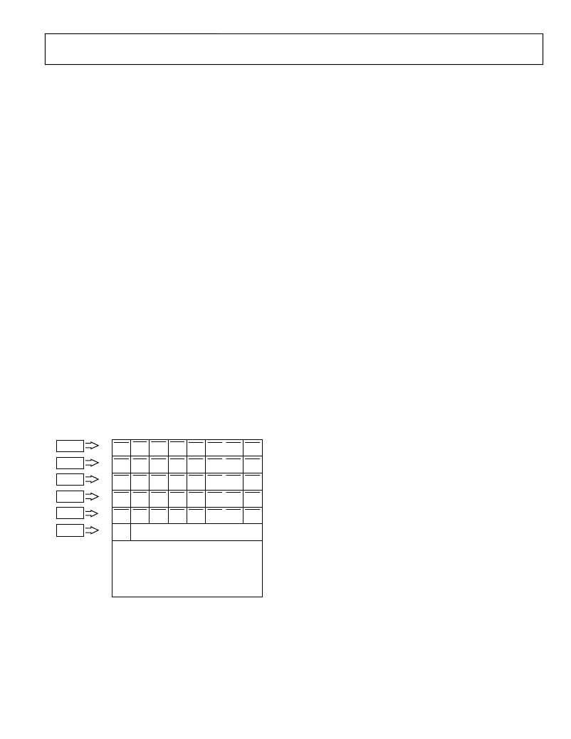
�for� the� groupings).� The� protection� bits� are� stored� in� the� last� flash�
�memory� locations,� Address� 0x3FFA� through� Address� 0x3FFF� (see�
�Figure� 81);� four� bytes� are� reserved� for� write/erase� protection,�
�one� byte� is� for� read� protection,� and� another� byte� sets� the� protection�
�security� key.� The� user� must� enable� read� and� write/erase� protection�
�for� the� last� page� for� the� entire� protection� scheme� to� work.�
�Note� that� the� read� protection� does� not� prevent� MOVC�
�commands� from� being� executed� within� the� code.�
�There� is� an� additional� layer� of� protection� offered� by� a� protection�
�security� key.� The� user� can� set� up� this� security� key� so� that� the�
�protection� scheme� cannot� be� changed� without� this� key.� Once�
�the� protection� key� has� been� configured,� it� cannot� be� modified.�
�Enabling� Flash� Protection� by� Code�
�The� protection� bytes� in� the� flash� memory� can� be� programmed�
�1.�
�2.�
�3.�
�4.�
�5.�
�Set� up� the� EADRH,� EADRL,� PROTB1,� and� PROTB0�
�registers� with� the� write/erase� protection� bits.� When� erased,�
�the� protection� bits� default� to� 1� (like� any� other� bit� of� flash�
�memory).� The� default� protection� setting� is� for� no� protection.�
�To� enable� protection,� write� a� 0� to� the� bits� corresponding� to�
�the� pages� that� should� be� protected.�
�Set� up� the� PROTR� register� with� the� read� protection� bits.�
�Note� that� every� read� protection� bit� protects� four� pages.�
�To� enable� the� read� protection� bit,� write� a� 0� to� the� bits� that�
�should� be� read� protected.�
�To� enable� the� protection� key,� write� to� the� PROTKY� register.�
�If� enabled,� the� protection� key� is� required� to� modify� the�
�protection� scheme.� The� protection� key,� Flash� Memory�
�Address� 0x3FFA,� defaults� to� 0xFF;� if� the� PROTKY� register�
�is� not� written� to,� it� remains� 0xFF.� If� the� protection� key� is�
�written� to,� the� PROTKY� register� must� be� written� with� this�
�value� every� time� the� protection� functionality� is� accessed.�
�Note� that� once� the� protection� key� is� configured,� it� cannot�
�be� modified.� Also,� note� that� the� most� significant� bit� of�
�Address� 0x3FFA� is� used� to� enable� a� lock� mechanism� for�
�the� watchdog� settings� (see� the� Watchdog� Timer� section�
�for� more� information).�
�Run� the� protection� command� by� writing� 0x08� to� the�
�ECON� register.�
�Reset� the� chip� to� activate� the� new� protection.�
�using� the� flash� controller� command� and� programming� ECON� to�
�0x08.� In� this� case,� the� EADRH,� EADRL,� PROTB1,� and� PROTB0�
�bytes� are� used� to� store� the� data� to� be� written� to� the� 32� bits� of� write�
�protection.� Note� that� the� EADRH� and� EADRL� registers� are� not�
�used� as� data� pointers� here� but� to� store� write� protection� data.�
�To� enable� read� and� write/erase� protection� for� the� last� page� only,� use�
�the� following� 8052� code.� Writing� the� flash� protection� command�
�to� the� ECON� register� initiates� programming� of� the� protection�
�bits� in� the� flash.�
�;� enable� read� protection� on� the� last� four�
�EADRH�
�EADRL�
�0x3FFF�
�0x3FFE�
�WP�
�31�
�WP�
�23�
�WP�
�30�
�WP�
�22�
�WP�
�29�
�WP�
�21�
�WP�
�28�
�WP�
�20�
�WP�
�27�
�WP�
�19�
�WP�
�26�
�WP�
�18�
�WP�
�25�
�WP�
�17�
�WP�
�24�
�WP�
�16�
�pages� only�
�MOV� PROTR,#07Fh�
�PROTB1�
�PROTB0�
�0x3FFD�
�WP�
�15�
�WP�
�WP�
�14�
�WP�
�WP�
�13�
�WP�
�WP�
�12�
�WP�
�WP�
�11�
�WP�
�WP�
�10�
�WP�
�WP�
�9�
�WP�
�WP�
�8�
�WP�
�;� set� up� a� protection� key� of� 0A3h.� This�
�command� can� be�
�PROTR�
�0x3FFC�
�7�
�RP�
�6�
�RP�
�5�
�RP�
�4�
�RP�
�3�
�RP�
�2�
�RP�
�1�
�RP�
�0�
�RP�
�;� omitted� to� use� the� default� protection� key�
�of� 0xFF�
�PROTECTION� KEY�
�0x3FFA�
�PROTKY�
�0x3FFB� 31:28� 27:24� 23:20� 19:16� 15:12� 11:8� 7:4�
�WDOG�
�LOCK�
�0x3FF9�
�3:0�
�MOV� PROTKY,#0A3h�
�;� write� the� flash� key� to� the� FLSHKY� register�
�to� enable� flash�
�;� access.� The� flash� access� key� is� not�
�configurable.�
�0x3E00�
�Figure� 81.� Flash� Protection� in� Page� 31�
�MOV� FLSHKY,#3Bh�
�;� write� flash� protection� command� to� the� ECON�
�register�
�MOV� ECON,#08h�
�Rev.� 0� |� Page� 91� of� 128�
�发布紧急采购,3分钟左右您将得到回复。
相关PDF资料
ADE7569ASTZF16
IC ENERGY METER MCU 16K 64LQFP
ADE7752BARWZ-RL
IC ENERGY METERING 3PHASE 24SOIC
ADE7755ARSZ
IC ENERGY METERING 1PHASE 24SSOP
ADE7757ARNZRL
IC ENERGY METERING 1PHASE 16SOIC
ADE7758ARWZRL
IC ENERGY METERING 3PHASE 24SOIC
ADE7761AARSZ-RL
IC ENERGY METERING 1PHASE 20SSOP
ADE7761BARSZ-RL
IC ENERGY METERING 1PHASE 20SSOP
ADE7768ARZ-RL
IC ENERGY METERING 1PHASE 16SOIC
相关代理商/技术参数
ADE7566
制造商:AD 制造商全称:Analog Devices 功能描述:Single-Phase Energy Measurement IC with 8052 MCU, RTC, and LCD Driver
ADE7566ACPZF16
制造商:AD 制造商全称:Analog Devices 功能描述:Single-Phase Energy Measurement IC with 8052 MCU, RTC, and LCD Driver
ADE7566ACPZF161
制造商:AD 制造商全称:Analog Devices 功能描述:Single-Phase Energy Measurement IC with 8052 MCU, RTC and LCD driver
ADE7566ACPZF162
制造商:AD 制造商全称:Analog Devices 功能描述:Single-Phase Energy Measurement IC with 8052 MCU, RTC, and LCD Driver
ADE7566ACPZF16-RL
制造商:AD 制造商全称:Analog Devices 功能描述:Single-Phase Energy Measurement IC with 8052 MCU, RTC, and LCD Driver
ADE7566ACPZF16-RL1
制造商:AD 制造商全称:Analog Devices 功能描述:Single-Phase Energy Measurement IC with 8052 MCU, RTC and LCD driver
ADE7566ACPZF16-RL12
制造商:AD 制造商全称:Analog Devices 功能描述:Single-Phase Energy Measurement IC with 8052 MCU, RTC, and LCD Driver
ADE7566ACPZF8
制造商:AD 制造商全称:Analog Devices 功能描述:Single-Phase Energy Measurement IC with 8052 MCU, RTC, and LCD Driver